Antenna Craft Y10-7-13 versus Stellar Labs 30-2476 |
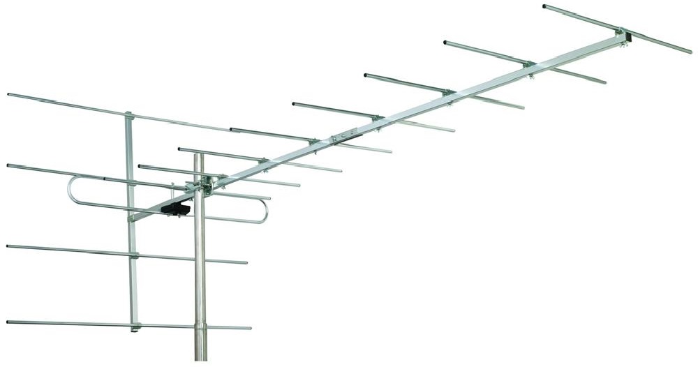
This is a comparison of the well known (but now discontinued) Y10-7-13 Hi-VHF Yagi to the newer and similar yagi design from Stellar Lab's model 30-2476.
| Y10-7-13 | 30-2476 |
 |
 |
Channels 7, 8, and 13:
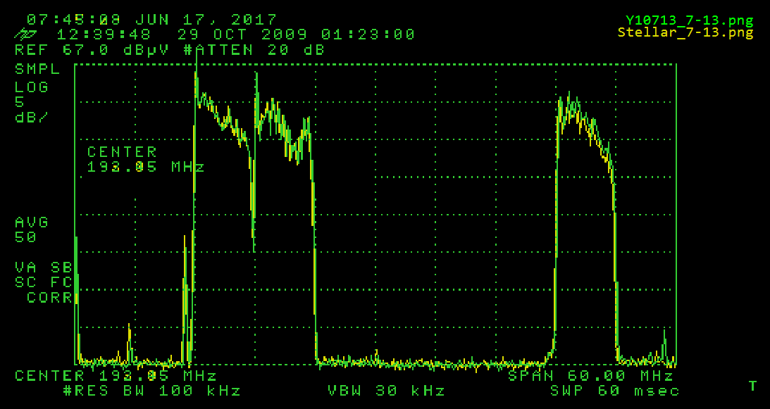
As for other comparisons this view overlays (merges) the captures of the two antennas onto each other. No significantly discernable differences are apparent at the low end of the band. At the upper end the Y10-7-13 trace is noticeably above the Stellar Labs 30-2476, by something between 1 and 1.5 dB. So, fairly similar sensitivities.
A Different Look at VHF 7, 8, and 13.
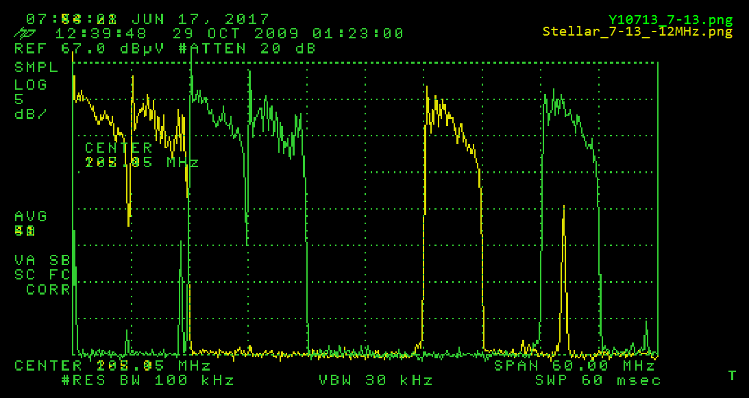
In this view I shifted center frequency of the Spectrum Analyzer by 12MHz before taking the capture for the Stellar Labs 30-2476 (yellow trace), effectively moving the channel positions in the display 12MHz to the left. This capture is then merged with the same Y10-7-13 capture as above, thus aligning the 30-2476 capture to the left of the Y10-7-13's. This was just to provide another visual for evaluating the differences. The (yellow) spike under the green (Ch 13) signal is a chance transmission burst at around 224-225MHz, in one of the Amateur, Radiolocation, or Mobile bands just above the Hi-VHF band. [It is above the Hi-VHF Band].
And Now For Something Completely Different - Any UHF Sensitivity?
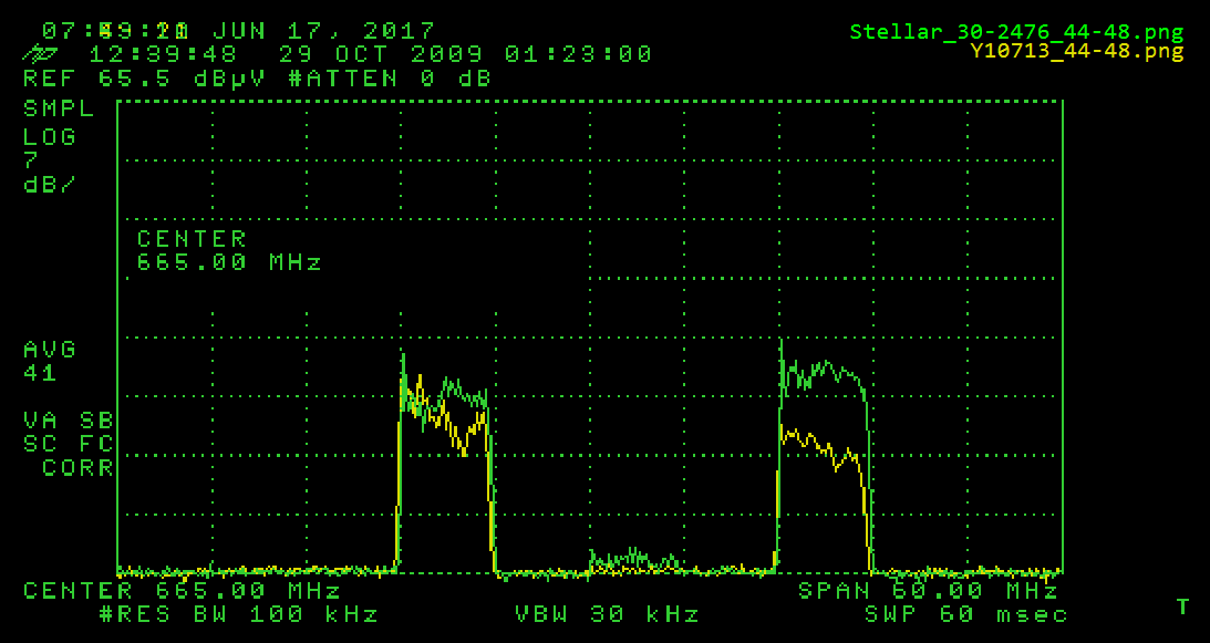
For grins the antenna(s) were kept pointed in the same direction, and captures were taken in this Channel 44-48 range, knowing there were a few fairly hot carriers in the band. To be clear though, the carrier on UHF 44 is about 70 degrees off axis, and likely the result of a serendipitous side lobe, while the carrier on 48 is line of sight (no knife edge).
Noting the vertical axis is 7 dB/division in this capture, the observation is about 7-8 dB higher sensitivity for the 30-2476 over the Y10-7-13. Note also there is another 1 Knife Edge carrier on Channel 46 that is noticeable on the (green) 30-2476 trace but barely noticeable on the Y10-7-13 trace.
Conclusions
At the low end the sensitivity of the 30-2476 is for all practical purposes identical to that of the Y10-7-13. At the upper end (Ch 13) the Y10-7-13 maintains a slight edge with about 1.0 to 1.5 dB higher sensitivity. That said, and assumming there are no nulls anywhere in the middle, this antenna's sensitivity is quite comparable to that of the Y10-7-13.
As food for thought, several design characteristics make this antenna an excellent candidate for vertical stacking, which would more than make up for that (slightly) lower high end gain.
- It's weight is approximately half that of the Y10-7-13.
- Because it's boom is smaller in all dimensions than the Y10-7-13's, it has less wind load.
- It's mounting bracket allows for adjustable forward/rearward positioning along the boom, as well as upward tilt positioning. Thus it allows for maintaing the elements of top and bottom (vertically stacked) antennas equidistant along the line of sight axis.
- It's low cost makes 2 antennas affordable.
The evidence is the 30-2476 is a viable alternative to the discontinued Y10-7-13. Further, for a few unique scenarios, the 30-2476 may have some usable UHF response.
Additional Observations and CommentsPackaging - Of two ordered antennas, both packages were slightly crunched at one end. On opening, the hardware of one was loose within the box. Two of the locking nuts for the center plates that join front and rear boom sections were missing, as was one of the nuts for the mounting bracket.
Construction - Nice. Well made parts, snug fits, no burrs, light weight. Overall length is shorter than the Y10-7-13, mainly due to the single versus dual folded dipole design, and the additional associated length. That said, its noteworthy that both are 7 director Yagi designs. The 30-2476 includes a built-in balun, versus the Y10-7-13's separate 300 to 75 ohm balun, and there is a convenient cable strain relief between balun and mounting bracket, which is much more substantial (more durable) than the Y10-7-13's. It also has a conveniently notched mounting bracket with stops at about 15 and 30 degrees allowing for upward tilt when necessary (sometimes an upward tilt helps to avoid proliferating VHF electrical interference).
Assembly - It's a little more detailed than the Y10-7-13 (more wing nut tightening than snap-into-place elements). But the assembly was straight forward, and each machine screw with Wing Nut thougfully includes a grommet placed on each screw after the Wing Nut, and this helps to prevent a spinning Wing Nut from travelling off the screw and into the grass somewhere.
Design - Two appealing factors over the Y10-7-13 are (1) the built-in balun (standard 75 ohm "F" connector output) and (2) the planar rear reflector which theoretically should provide better F/B ratio. [Also, perhaps, better immunity to VHF noise from the rear.] However and for the record, the original Y10-7-13 specifications indicate a gain of 9.4 dB and F/B Ratio of 16.5 dB. In contrast, the 30-2476 specifications found on MCM Electronics' web site indicate "Maximum gain: 14dB, and Maximum front/back ratio: 17dB". First of all, it is likely the 30-2476 numbers are dBi, not dB, secondly a -2.1 dB correction to the 30-2476 F/B ratio would contradict the F/B theory indicating poorer F/B ratio for the 30-2476, and thirdly even with a -2.1 dB correction to the Gain figure for the 30-2476 there would be an assertion of 2 dB or so better gain than the Y10-7-13. That assertion is not supported by this field comparison. [Another good example of the ambiguity and unreliability of manufacturer specifications].